Vickers 54 Viking Mk IV amphibious biplane
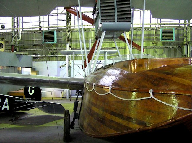
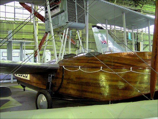
Not really a WW1 aircraft as it first flew just after World War One ended. It was designed for military use by Vickers. It is unusual in that it has a pusher propeller and a hand crafted wooden ship hull. It was driven by a Rolls Royce or Napier and sons Lion engine depending on the mark of Viking. The last amphibious Viking was built in 1923. This seaboat was used throughout the British Empire
Vickers first started research on designing their first amphibious single engine military aircraft in December 1918. Most Mark IV Vikings had a Napier Lion engine a 12-cylinder water-cooled broad arrow piston engine, 450 hp (336 kW). The seating arrangement consists of two pairs of side-byside seats in front of the wings, and one seat aft of the wings,bringing the total up to five, including pilot.. It had a wing span of 50 feet (15.24 m). Its maximum speed was 113 mph (98 knots 182 km/h) but it cruised at 91 mph. It could fly for 4hrs 45 min with a range of 450 miles before it needed to land and refuel. It could climb to 3,000ft ideal for aerial photography. For military use a machine gun was added to the front crew compartment on a swivel scarf gun ring.
The Vickers Viking IV was the first amphibian aircraft to be used in Canada and was the first aircraft purchased by the Canadian government after the First World War. Seeking to replace the Curtiss HS2-L, the government chose the Viking IV in 1923. Vickers in the United Kingdom built two and shipped them to Canada, while its Canadian subsidiary set up an aircraft manufacturing plant and built the remaining six in Canada. These were the first aircraft built in Canada following the First World War. A replica can be seen in the Alberta Aviation Museum.

Photograph taken at the Brooklands Museum, Weybridge, Surrey, England
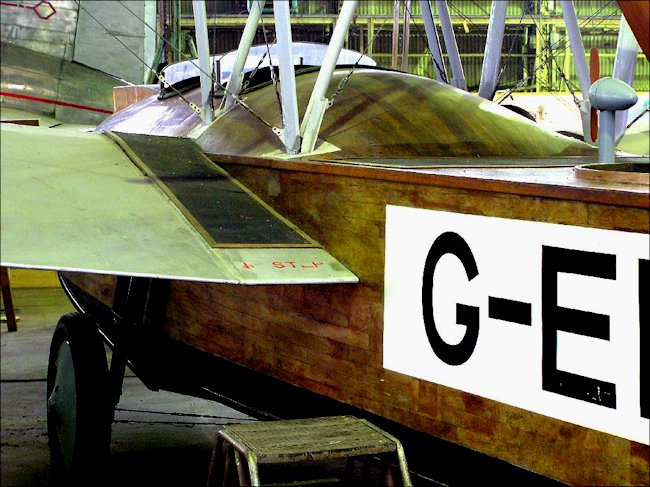
The Vickers Viking IV at the Brooklands Museum, Surrey England is G-EBED. The model company called Montex did produce a 1/72 scale model kit number RMA 720. When used by private companies an enclosing Triplex glass windowed cockpit cover called a coach roof was added for protection from the elements.
The early development of this seaplane has a history of deaths connected with it. The first death involved an early Vickers Viking I prototype, registered G-EAOV. Sir John Alcock died taking this aircraft or another early example to the Paris exhibition on 18 December 1919, whilst trying to land at Cote d'Everard, near Rouen, Normandy in foggy weather. Mr Ross Smith and J.M. Bennett (partners in the 1919 England to Australia flight) died on 13 April 1922 just outside the Brooklands racetrack near Weybridge in Surrey in a Vickers Viking IV. The last Viking amphibians were built during 1923.
The aircraft had a mahogany hull, which required that the aircraft be pulled out of the water each night and its hull oiled. The skills needed to build this aircraft were not just from the avionic industry. Boat building wood work craftsmen were employed to build the hull. Mr Saunders of Cowes invented the planking of mahogany built up on the "consuta" principle. The inner and outer skins have their strips at right angles to one another and each makes an angle of approximately 45 degrees with the line of flight. The main frames are also of mahogany, while the intermediate timbers and longitudinal stringers, as well as keel, chines and gunwales are of rock elm. In spite of the extra beam, the new hulls are very little heavier that the old marks due to chiefly the employment of thinner but closely spaced stringers.

Photograph taken at the Brooklands Museum, Weybridge, Surrey, England
The following is the observation of a 1921 observer of the then new Vickers Viking IV: In the bottom of the hull the stringers are spaced approximately three inches apart, while the sides do not call for the same strength and consequently have their stringers spaced much wider. The planking is through-fastened to stringers and timbers and screwed to the frames. In consequence of the use of consuta planking the work of planking the hull is stated to be very considerably less than the case of a boat built hull, and the only places where it is possible for a leak to occur is where the planking joins keel and chines. These joints being well laid in red lead, with fabric strip coverings between them and the outer keel and chines, there is scarcely any possibility of any appreciable leak anywhere.
The steps are vee-bottomed also, that is to say, there is no flattening out from bows to front step nor from front to rear step. The main (front) step is open, i.e. water is a owed to enter into the angle formed by the step bottom and the main planking. In the case of the rear step a different arrangement has been employed. The face of this step is closed, and the whole interior of the step is water- and airtight except for small vent holes inside the hull to prevent bursting.
Just aft of the rear step is a small water rudder and tail skid combined. The shape and general design of this water rudder will be gathered from the accompanying sketch. The rudder1 is sprung by an oleo-pneumatic combination, and has been found, in spite of its position, immediately aft of the step, where one might expect it to be working in very disturbed water, to be very effective, not only in the water but also when performing the function of a steering tail skid.

Photograph taken at the Brooklands Museum, Weybridge, Surrey, England
Except for minor improvements the amphibian gear remains almost identical with that of the older model. Certain parts have been strengthened up or simplified, but the general principle remains the same. The telescopic vertical tube carrying the wheel is pivoted at its upper end, "which has a wormwheel engaging with a worm on the end of a shaft running across the hull. This shaft is rotated by a wheel in front of the pilot via chains, and in rotating operates the vertical shaft which terminates at its lower end in a star wheel engaging with holes in the quadrant bolted to the sides of the hull. In rotating, the shaft swings the wheel forward and upward. As the arm of the wheel is long, and that of the operating shaft very short, the process of raising the wheel takes some little time. This, however, is of small importance, since there is scarcely any likelihood of the wheels having to be raised in a hurry.
Lowering the wheels is a performance occupying a few seconds only, and in case of engine failure while flying over land it is therefore an easy matter to lower the wheels before a landing has to be made. The lower ends of the telescopic tubes are housed in a phosphor-bronze casting which has a substantial lip gripping another casting permanently fixed on the hull, and with which it engages only when the wheel is right down. The outward pull caused by the wheel at this point is transmitted across the hull by special strutting and wiring in way of step, so that there should be no possibility of it pulling off, even in a rough landing.
One very important addition has been made to the landing .gear, i.e. the fitting' of band brakes. The manner in which these have been designed to allow of the upward travel of the wheels is most ingenious. The operating .gear consists of "two separate units. One remains fixed on the hull and the other travels up with the wheel. One of our sketches shows the gear, and is, we think, self-explanatory. The curved portion of the vertical rocker on the side of the hull is, of course, shaped to the arc of a circle having the main pivot as its centre and the distance from this to the end of the lower-system lever as radius. The whole is extremely neat and light, and must be the outcome of many other alternatives. The effect of the band brakes is to enable the machine to be pulled up in about a third of the distance required without the use of brakes, so that their fitting has evidently been extremely worthwhile. In order to avoid one brake being applied harder than the other a compensating device of the usual form has been incorporated. Flight 1920
Flying Boat books


Tweet